My First Circuit Board: Pong Video Game
CB
I was a teen-ager at the time and had built lots of small gadgets in my basement. I didn't always know how every transistor in a circuit worked, but I always had fun. My prototyping skills weren't exactly flawless, though, and my attempts at building projects like a Signal Generator or a Frequency Counter didn't always go well. I was largely limited by the money I could earn with my after-school lawn-mowing business, and saving for college was always on my mind. However, when I received the April 1976 Popular Electronics issue that described how to build a Pong Video game, I knew I had to make one.
I had already thought about building Pong and had sent away for plans to an advert in the back of Radio Electronics. I remember my heart sinking when I received the schematics. The design was absolutely daunting. It was 8 or 9 pages of densely hand-drawn logic circuits, totaling over 100 logic ICs. It was completely out of reach.
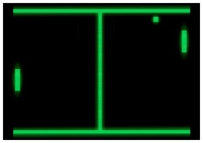
The Popular Electronics design was much more economical. It used about a dozen ICs for the basic game, and maybe eight ICs for the scoring circuit. Instead of creating the complex video timing and ball collision circuitry out of counters and logic, this circuit used analog oscillators, one-shots and comparators. Rather than displaying the score as numbers, it displayed two bars across the bottom of the screen. This was something I could both afford and build.
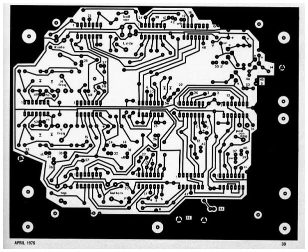
The Popular Electronics article included artwork for a single sided PCB. I had never made a circuit board before. I bought the etching kit from Radio Shack, the G10 circuit board laminate from Poly Paks, and most of the chips from Solid State Sales. The rest of the parts I salvaged from electronics I had picked off the streets on garbage day.
In those days, the only way that a hobbyist could make a board was by putting black tape directly on a board. I bought a layout kit with a variety of IC pad layouts, pads and tape, and proceeded to track out the board. It took me many evenings to carefully copy the layout from the magazine pages. I was pretty anxious about etching the board and finally decided to take a spare piece of laminate and do a few experiments. This was fortunate, as I discovered that the tape adhesive would peel off the board if the etching took too long. I found some articles on making circuit boards in my stack of electronics magazines and, with some experimentation, learned that pretty good results could be gotten if I heated the etch and rocked it gently. When I think back, I still can't believe that my Mom let me use her Pyrex casserole dish and kitchen oven to heat up the etchant!
The board came out surprisingly well. I had under-etched the board slightly, and the little holes in the center of the copper pads hadn't fully etched. These holes were supposed to center the bit when drilling the holes. Instead, I sharpened a nail and used it as a center punch, and then carefully drilled the holes, breaking a few expensive bits in the process.
At the time, there wasn't an easy way to get a video signal into a TV. Most video games interfaced to TVs by using RF modulators set to channel 2 or channel 3. I had fixed a few TVs and understood enough about how they worked that I could inject the video signal directly into the composite video circuit. TVs were still built with isolation transformers, so it was safe to be probing around inside a set. I don't remember how I debugged the circuit. I can't imagine it worked the first time. I didn't have an oscilloscope, but I did have a Triplett voltmeter and a home-brew logic probe. Eventually, though, it did work. My friends and I had a ton of fun playing with the game. Our family struggled to make ends meet and we never had any of the latest stuff. For once in my life, I, the geeky kid on the block, had the latest and most wanted toy. Ahhh, the sweet smell of success….
- Shared November 16, 2012